Example: Adding an FFT Module
To make it easier to understand how to add a custom module, an example is provided for the LimeSDR XTRX. In this example, a fixed-point FFT module is inserted in the data receive path so that the results of the Fourier transform are packed into packets instead of raw RF samples. Since LiteX provides a flexible framework for defining hardware configurations through command-line arguments, the --with-fft argument is used to modify rx_path and include an FFT example when building the project.
If you want to try out the FFT module without modifying code, you could build the target with the following command:
python3 -m boards.targets.<target> --build --with-fft [--load] [--cable <cable>]
All sources required for the example are located in gateware/examples/fft. The folder contains:
fixedpointfft.py A modified fixed-point FFT module based on the amlib repository.
fft.v The Verilog source file (pre-generated from fixedpointfft.py).
fft_wrap.vhd A VHDL wrapper for fft.v that provides a basic AXI-STREAM interface.
LimeFFT.py LiteX wrapper file incorporating the FFT module.
limesdr_fft_samples.grc A GNU Radio file containing blocks that scale, shift, and display the FFT data received from the board.
xtrx.ini LimeSDR XTRX board setup file for GNU Radio
mini.ini LimeSDR Mini V2 board setup file for GNU Radio
In the standard design (see the LimeSDR XTRX gateware description), raw samples are received by lms7002_top and then passed to rx_path_top for packetization. To reuse this logic and insert the FFT module, the FFT module should be placed between lms7002_top and rx_path_top.
Below is a block diagram showing the desired structure. New elements are highlighted in green, and elements to be removed are marked in red.

Any new modules inserted into the data path have to be compatible with the modules that that they are inserted between. LimeDFB documentation contains descriptions of modules used in the data path, as well as detailed waveforms for common operating modes. Waveforms are provided for lms7002_top, rx_path_top, tx_path_top.
Instantiating FFT Example module
This code snippet below from gateware/LimeTop.py file adds an FFT example to the design when the with_fft flag is enabled.
# FFT example --------------------------------------------------------------------------------------
if with_fft:
    # Define Reset signal
    fft_reset_n = Signal()
    # Connect newly defined reset signal to main rx path reset trough MultiReg
    self.specials += MultiReg(self.fpgacfg.rx_en, fft_reset_n, odomain=self.lms7002_top.source.clock_domain)

    # Instantiate FFT module
    self.fft_example = LimeFFT(platform=platform,
                               sink_clk_domain=self.lms7002_top.source.clock_domain,
                               source_clk_domain=self.lms7002_top.source.clock_domain)

    # Connect reset signal to FFT module
    self.comb += self.fft_example.reset.eq(~fft_reset_n)
Connecting FFT Example module
To avoid conflicting assignments, you must disconnect the lms7002_top master interface from the rx_path_top slave interface. In code snippet below you can check how rx_pipeline is modified and --with-fft argument is used in gateware/LimeTop.py file to insert FFT module:
# LMS7002M -> [LimeFFT example] -> RX Path -> Sink Pipeline.
if with_lms7002 and with_rx_tx_top and with_fft:
    # LMS7002M -> RX Path -> Sink Pipeline.
    self.rx_pipeline = stream.Pipeline(
        self.lms7002_top,
        self.fft_example,  # Inserting FFT module
        self.rxtx_top.rx_path,
        self.source,
    )
elif with_lms7002 and with_rx_tx_top:
    self.rx_pipeline = stream.Pipeline(
        self.lms7002_top,
        self.rxtx_top.rx_path,
        self.source,
    )
Checking FFT results
After these modifications, build the project and program the board as described in Building the Project.
The FFT results can be observed using the limesdr_fft_samples.grc file provided with the example. Ensure that you have up-to-date versions of GNU Radio and LimeSuiteNG installed.
Before running flowgraph modify board_ini variable with correct setup file:
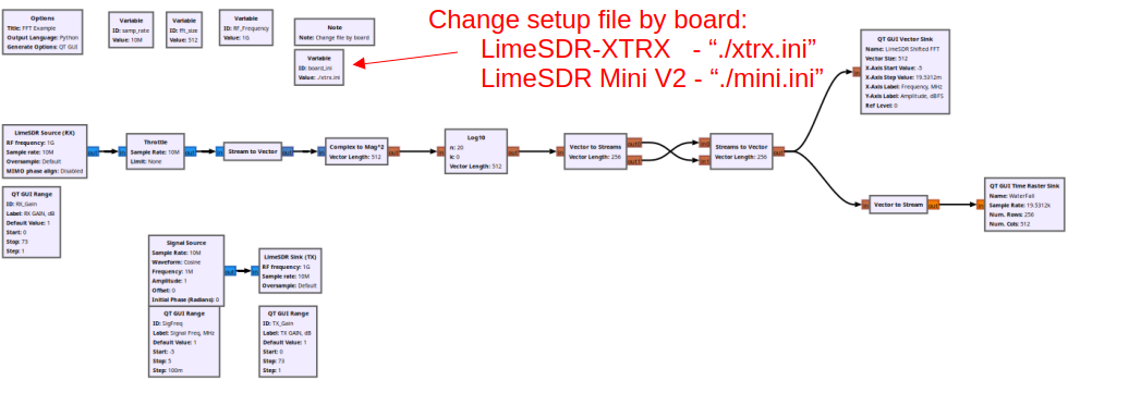
If an RF cable is connected in a loopback configuration, linking the RX and TX of Channel A, output in GNU Radio should look like in figure below, it should also react to interactions with the Signal Frequency, TX Gain, RX Gain sliders.
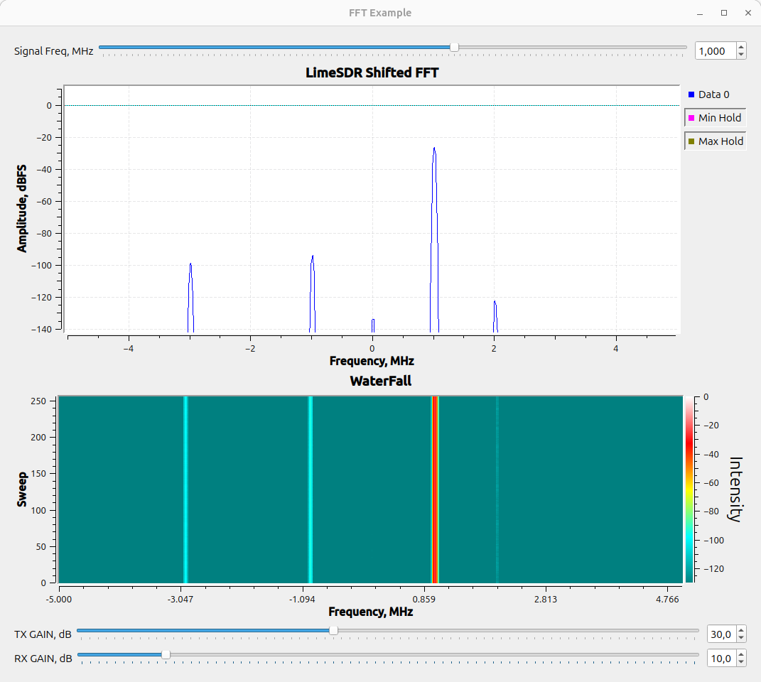
Note
TX Gain, RX Gain settings might differ for different boards.
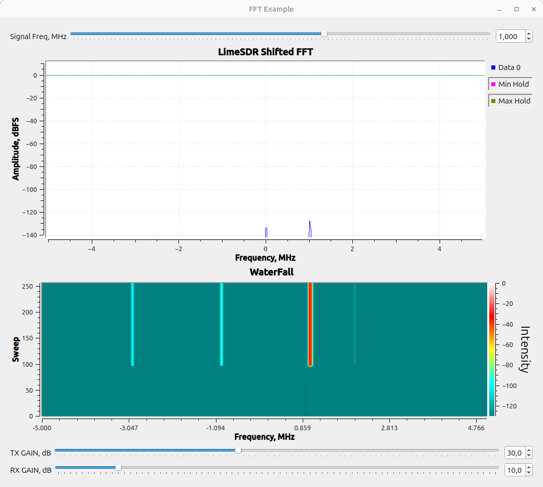
However, if no cable is connected, or the cable is connected improperly, the output should look like in figure below.